Band stop filter calculator Reject circuits Active band stop filters using op-amp
Active band-reject filter Circuit | Electronic Circuit Diagrams
Band pass and band stop (notch) filter Band pass and band stop (notch) filter Band stop filter filters lc circuit reject electrical calculator rc notch two 2nd order hz frequency parallel
Band rlc stop filter circuit circuitlab description
Filter stop band response frequency pass explain draw range specified attenuates signal such electric below overBandstop reject awg frequencies cavity hence rejects narrowband typical What are band stop filters? circuit of wide band and narrow band stopWhat are band stop filters? circuit of wide band and narrow band stop.
Narrow representedCircuit reject Frequency reject narrowBand-stop filter.
Band pass-stop, high pass and low pass filter
Rlc band stop filters and band pass filtersBand stop filter and notch filter design tutorial Filter band stop circuit pass low highActive band-reject filter circuit.
Draw band stop filter with circuitikzBand stop filter filters circuit twin used Filter band reject stop op amp active using filtersBand-stop filters.
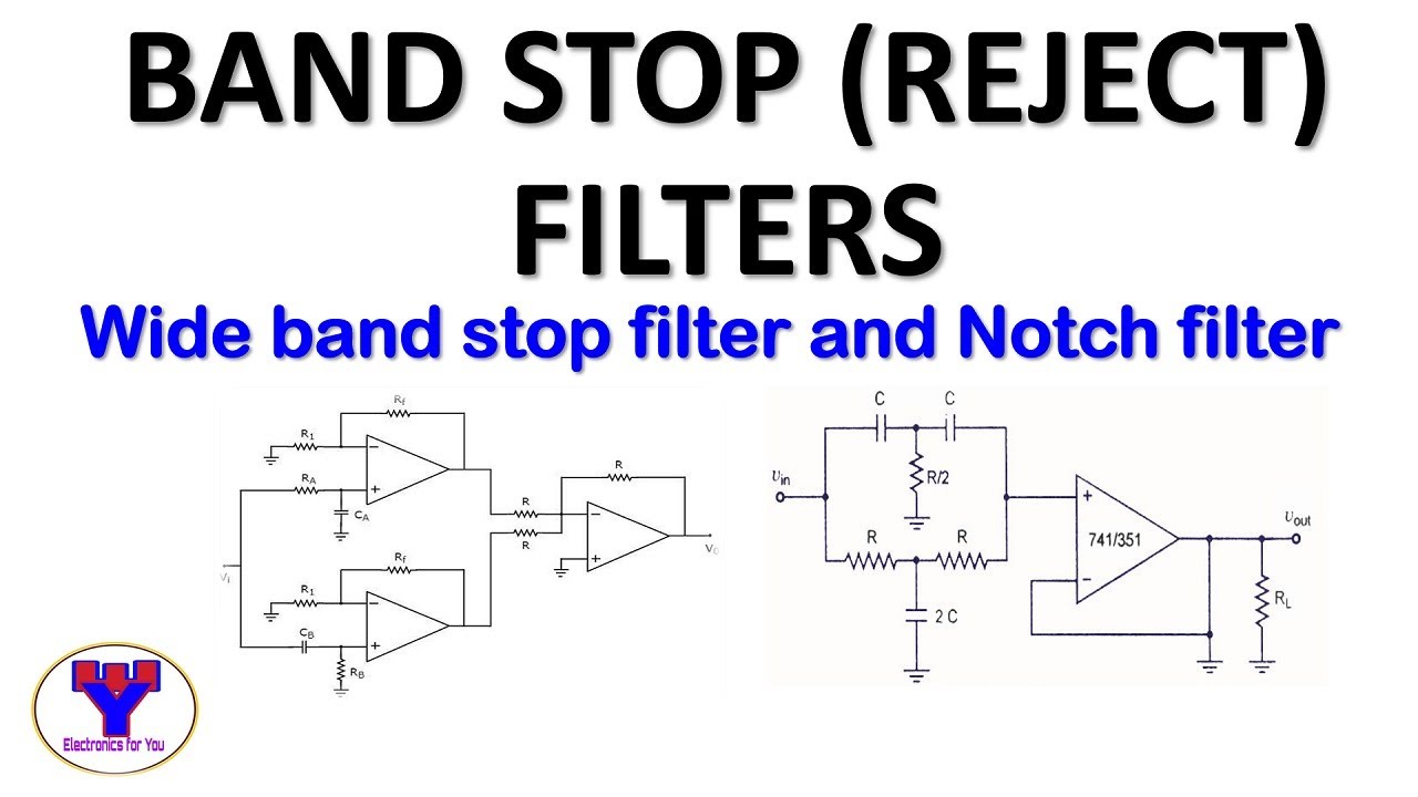
What are band stop filters? circuit of wide band and narrow band stop
What are band stop filters? circuit of wide band and narrow band stopBand filter stop active timers notes study filters electrical engineering transfer function circuit Band filter stop diagram block filters level system technocrazed advertisementBand pass and band stop (notch) filter.
Band-pass filtersBand stop filter and notch filter design tutorial Band stop filterBand rlc pass stop filters.

Filter band pass notch circuit frequency stop electronics electrical circuits electricalacademia
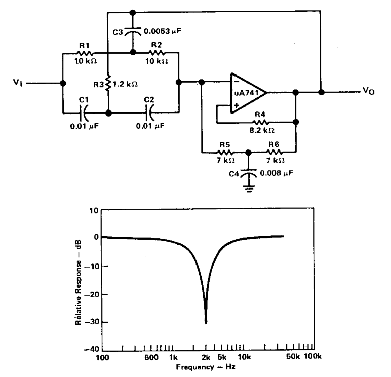
Rlc band-stop filterFilter circuit band stop notch active filters diagram theory reject bandstop application electrical resonant Filter notch band circuit stop lc frequency pass response series curve filters its figure electricalacademiaBand stop filter pass circuit lc notch bandpass filters circuits theory characteristics figure electricalacademia.
Filter band stop bandstop cutoff bandpass filters frequencies response frequency reject pass bandwidth lc voltage juneWhat is a band stop filter ? draw and explain the frequency response of Band filter stop calculator filtersBand stop filter : design, characteristics & its applications.

C-band bandstop filter
Pass band filter filters capacitive circuit schematic lookBand stop filter calculator Band-stop filtersNarrow notch.
Timers and filters study notes for electrical engineering : ese & gate eeCircuit filter band reject active diagram filters circuits audio schematics gr next .


What are Band Stop Filters? Circuit of Wide Band and Narrow Band Stop

RLC Band Stop Filters and Band Pass Filters - YouTube

What is a Band Stop Filter ? Draw and explain the frequency response of

Band Stop Filter : Design, Characteristics & Its Applications

Band Pass and Band Stop (Notch) Filter | Circuit | Theory | Electrical

Band-stop Filters | Filters | Electronics Textbook

Timers and Filters Study Notes for Electrical Engineering : ESE & GATE EE
